History of Thermistor Development
- Michael Faraday found the negative temperature coefficient of Ag2S in 1833.
- Labs of Philips, Siemens, etc. started studying NTC characteristics of oxide materials like Fe3O4, UO2 in the early 1930s
- Materials like NiO, CoO, Mn2O3 were adopted in the late 1930s to the early 1930s
- Bell Telephone Laboratories reached the initial application stage in the late 1940s, and afterwards, its development and applications were
expanded with material composition. It was proven that two or more transition metal oxides like Co, Mn, Ni, Cu, Fe can adjust resistivity
and temperature coefficient according to composition rate, which facilitated its commercialization.
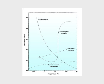
What is an NTC thermistor?
- It means a thermally sensitive resistor which has a negative temperature coefficient where resistance value decreases as temperature
increases. It is a semiconductor sintered at a high temperature of 1200℃~1400℃ after mixing and formation of two or more transition metal
oxides (Co, Mn, Ni, Cu, Fe), that forms a Spinel structure of AB2O4, and mainly uses Ag, Pt, etc. as its electrode,
- For lower temperatures, Mn, Co and Ni are used. For higher temperatures, Al, Zn, Mg, Cr, etc. are added to Co and Mn, or CeO2 and ZrO2 are used.
No-load resistance ratio (Ro@T)
is the DC resistance value without electrical heat dissipation at a specified temperature. To measure this value, thermistor heat dissipation should be limited so that the change of DC resistance value is within ±0.01% though heat dissipation.
Resistance ratio (Ro@T₁/Ro@T₂)
is a ratio of two no-load resistance values at two certain temperatures T₁, T₂
Temperature coefficient of resistance (α@T)
is a coefficient which indicates the change of thermistor resistance per 1℃ of temperature at certain temperature T and has the unit of %/℃
- α@T = 1/R@T ˚ Dr@T/Dt = - β/T
- α@T: temperature coefficient of resistance (%/℃)
R: resistance value at absolute temperature T(K)
β: B constant
Thermal time constant (τ)
Thermal time constant (τ) is a constant which indicates the speed of change of the thermistor resistance value for rapid changes of ambient temperature, and it shortens as heat capacity for ambient condition change decreases. Thermal time constant of the thermistor is related to thermistor heat capacity C and heat dissipation constant δ, and the following relationship is established when the thermistor temperature changes from the initial temperature (Ti) to the final temperature (Te).
-CdT = δ(T-Te)dt ---(1)
Dt/dt = -δ/C X (T-Te) ---(2)
If we solve the above equation (2) as a differential equation according to Newton's Law of Cooling
we get T - Te = (Ti -Te)exp(-t/τ) ---(3)
Here, if we call t=time and τ=thermal time constant, τ=C/δ. If we assume t is equal to τ in expression (3) then
(T - Te)/(Ti - Te) = exp(-1) = 1/e = 1/2.718 = 1 - 0.632
Therefore
T - Te = (Ti -Te) X (1-0.632)
T = -0.632(Ti -Te) + Ti
Thermal time constant is generally indicated as a maximum, and the medium or mounting method, etc. where a thermistor is located should be specified as the constant depending upon heat transfer speed when measured as in heat dissipation.
Thermistor temperature changes according to elapsed time after the change in ambient temperature are as follows.
| Elapsed time t |
Temperature change of thermistor |
| τ |
0.6321(Ti - Te) |
| 2τ |
0.8647(Ti - Te) |
| 3τ |
0.9502(Ti - Te) |
| 4τ |
0.9817(Ti - Te) |
| 5τ |
0.9933(Ti - Te) |
| 6τ |
0.9975(Ti - Te) |
| 7τ |
0.9991(Ti - Te) |
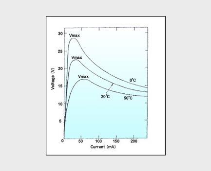
Peak Voltage (Vp)
Peak Voltage (Vp) is the point where voltage is at its peak and starts to decrease as current increases in the current-voltage characteristics of a thermistor, that is, de/dl=0.
Maximum usable temperature
Maximum usable temperature is the maximum temperature to which thermistor characteristics are stable for long-term use.
Maximum rating
Maximum rating is the maximum power of a thermistor to which thermistor characteristics are stable for long-term use.
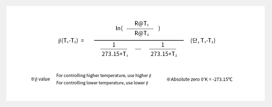
B constant(β)
B constant(β) is a material constant of a thermistor, and a constant which indicates the size of resistance change for temperature change between two certain temperatures (T1, T2) in resistance-temperature characteristic. It is expressed as follows
Thermal dissipation constant (δ)
means the ratio of thermistor-generated heat to thermistor temperature change at A certain ambient temperature, power required for increasing thermistor temperature by 1℃ by self-heating, which has the unit of ㎽/℃. The δ value depends upon thermistor shape, attachment, surrounding medium, etc., and unless otherwise specified, it is defined as the power required for temperature increase by self-heating from an ambient temperature of 25℃ to 75℃ within the thermostatic bath with more than 1,000 times the volume as the thermistor volume to be measured, divided by a temperature increase (ΔT) of 50℃. It is calculated by the following expression.
W = V X I = δ(Ta - To), δ = W/(Ta - Yo) = I²R/(Ta - To) = P/ ΔT
(Ta: ambient temperature, To: heat-generating temperature, W: power consumed for heat generation)
1. Use-specific thermistor design
- Set basic characteristic resistance and B constant values based upon the center value of used temperature range and use temperature area.
- For lower temperature use, it is desirable to have relatively low resistance and B constant and higher temperature and precision measurement use should have high resistance and B constant
- For used part, select thermistor type which can accept the speed of temperature increase or decrease.
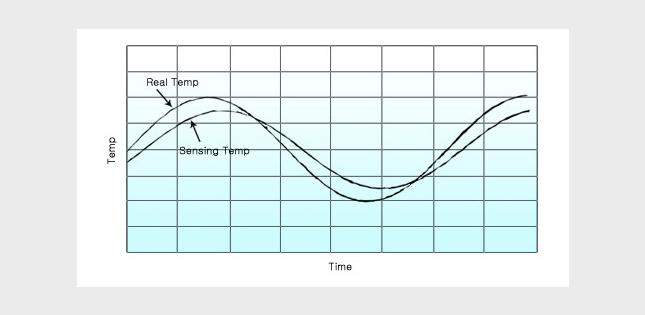
2. Consideration of heat following characteristics
According to use, thermistor-using ‘Sensor Ass’y’ varies in form including metal tube or resin sealing, and this has great influence on the heat
following characteristics during real use. Therefore, it should be designed on the basis of average speed of temperature increase or
decrease in the part to be used, and delay time which occurs between real temperature and sensed temperature should be calculated and applied.
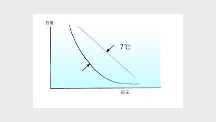
3. Linearization
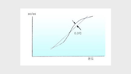
In principle, the temperature resistance of thermistors has a non-linear change curve. As the non-linearity could reach a maximum of 7℃, it
must be linearized, and after linearization, non-linearity can be adjusted to below 0.37℃.
As a result of linearization, use temperature range should correctly match with the linearization area, and this work can be done by thermistor F(t) characteristic. The F(t) characteristic is calculated by the following method.
4. Consideration of rated power
After linearization, current and voltage conditions applied to the circuit should be checked on the basis of maximum use temperature, and thermistor self-deterioration by the application of power over rated power should be suppressed.
5. Selection of error range
Selection of the allowable error range of a thermistor should be specified for resistance and B constant, and this should be expressed as an error in the range of use temperature, not at one specified temperature.
1. Resistor-temperature characteristic
Resistor-temperature characteristic is the relationship between temperature given to a thermistor itself and the no-load resistance of the thermistor. This characteristic can be approximately expressed as follows
- R@T = R@To exp β(1/T - 1/To)
- R@T: resistance value at absolute temperature T(K)
R@To: resistance value at absolute temperature To(K)
β: B constant of thermistor
T, To: absolute temperature ( K=℃+273.15)
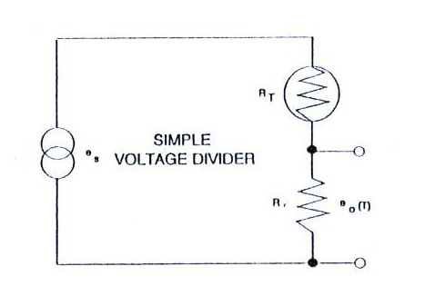
2. Current-voltage characteristic
Current-voltage characteristic is the relationship between thermistor current and voltage at a certain temperature. In the region of a very small current, voltage is proportional to current and linearly expressed according to Ohm's Law as self-heating of the thermistor is small. As current increases, however, voltage starts to decrease. It also means De/Di continues to decrease.
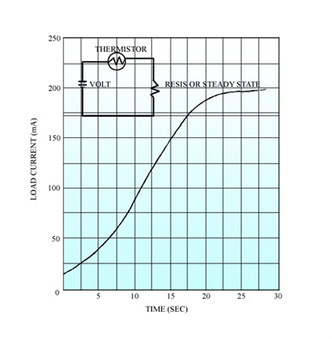
3. Current-time characteristic
Resistance is not immediately reduced even if sufficient current is applied for self-heating of a thermistor, and also, time delay surely occurs before equilibrium is reached when the thermistor is excited in the equivalent circuit. This is called the current-time characteristic. This characteristic depends upon thermistor heat dissipation, heat capacity, and circuit configuration.


 PRODUCTS


 PRODUCTS